
![]() - Download PDF-
- Download PDF-
SEEFOR 10 (2): 181-185
Article ID: 227
DOI: https://doi.org/10.15177/seefor.19-10
PRELIMINARY COMMUNICATION
Modernization of Harvesting and Processing Head
Konstantin Pavlovich Rukomojnikov1*, Sergei Vladimirovich Vedernikov1, Victoriia Olegovna Kuptcova1
(1) Volga State University of Technology, Department of technology and equipment for timber and chemical industries, Lenin Sq., b. 3., RU-424 000 Yoshkar-Ola, Russia
Citation: RUKOMOJNIKOV KP, VEDERNIKOV SV, KUPTCOVA VO 2019 Modernization of Harvesting and Processing Head. South-east Eur for 10 (2): 181-185. DOI: https://doi.org/10.15177/seefor.19-10
Received: 22 Oct 2018; Revised: 18 Jan 2019; 4 May 2019; Accepted: 11 Jun 2019; Published online: 14 Aug 2019
Cited by: Crossref Google Scholar
Abstract
Background and Purpose: The article is devoted to the reduction of energy consumption necessary for delimbing.
Materials and Methods: Branch delimbing method includes feeding the tree trunk through the ring formed by the delimbing knives and simultaneous reciprocator movement of the delimbing knives along the axis of the processed trunk. The distinctive feature of the construction is the presence of the beater unit comprising a pusher and a piston mounted inside a sealed housing.
Results: As a result of the suggested construction the force of the beater impact of the delimbing knife is increased. Using this method, the branches are removed not only due to the force generated when the knives come in contact with branches pushed by feed rolls moving the trunk, but also due to extra beater stress affecting the delimbing knife. The use of the aforesaid method and the construction of the mechanism allows to reduce energy consumption necessary for the delimbing process.
Conclusions: The design of harvesting and processing head proposed in this article can be used in the design and manufacture of logging machines and mechanisms. The technical solution may be an interesting advance of the delimbing process when processing trees, especially when cutting big branches or when cutting forces are temporarily higher than average force values.
Keywords: forestry machinery, harvester head, delimbing mechanism, tree, harvester, processor
INTRODUCTION
A shift of harvesting enterprises to progressive logging technologies ensures enhancing the productivity, improving the quality of the logging site processing and minimizing negative environmental impact. Over the past decade forestry machinery pool has significantly expanded and become diverse all over the world. Ever increasing requirements for such equipment force manufacturers to constantly improve forestry machinery. One of the most promising and intensively developing technological processes of timber harvesting are technological processes which use state-of-the-art harvesting machinery capable to remove branches from tree trunks on the logging site (harvesters and processors) [1].
Summing up the aforesaid, it is worthwhile to note that modernization of harvester and processor technological equipment is vitally important and has a valuable scientific and practical value.
LITERATURE REVIEW
Many researchers are involved in searching for solutions to improve the structure of the working elements of harvesting machines [2-6] and modern machines working in close connection with them [7-11]. Based on the functional and technological analysis of harvester head, Budnik [12] and Demchuk [13] devise a development matrix, which contains all possible ways for its improvement. Among other ways of efficiency enhancement of the harvester head operation we consider it to be necessary to reduce the impact of dissipative forces emerging during trunk feeding process.
At present, delimbing methods and the construction of mechanisms patented in [14-17] using the feeding wheels mounted on the movable gripping device and the delimbing device ensure the removal of branches on the side adjacent to the mechanism case. The feed rollers embrace the tree trunk from both sides and force the tree trunk with the effort necessary to remove branches by the delimbing knives. The dependence on the feed roller drive with sufficient delimbing capacity is a significant drawback of aforesaid method and the construction of the mechanism.
Another delimbing method presented in the patent publications [18-20] comprises the use of three feeding rolls, one of which is mounted on the frame structure, while the other two are mounted on the movable gripping elements. The device ensures increased feeding force. The branches are removed through the impact force emerging when the feeding rolls move in the absence of additional mechanical impact on the branches. It means that the feed roller drive should have the increased capacity, which again represents a significant drawback of the aforesaid method and the construction of the mechanism.
Attempts to create vibrations of the cutting tool to influence the processes of mechanical processing of wood have been known since the 1940s. They are among the options for reducing the energy consumption necessary for delimbing.
Auto-resonant ultrasound technologies alongside with vibration technologies in general are characterized by high performance, efficiency and productivity, as they allow the obtaining of the maximum possible amplitudes of the working body (or other defining characteristics) with minimum power expenditures [21]. Ultrasonic-assisted cutting experiments have been performed on different wood species in dry and wet state. Compared to conventional cutting, the reduction of cutting forces by 50% is achieved at relatively small vibration amplitudes of 8 μm. [22].
However, ultrasonic cutting of wood has not yet found wide practical application for several reasons: the complexity of the development of ultrasonic oscillatory systems for the implementation of the processes of machine cutting; high cost and low reliability of ultrasonic equipment (ultrasonic generators and emitters) [23].
At the same time, high-performance perforators, original designs of vibration-damping devices and new designs of percussion mechanisms were developed and introduced into mass production. In the system of pneumatic impact mechanism, an increase in the working pressure is achieved through the use of compressed air. The increase in shock power by 2.8 times theoretically corresponds to an increase in air pressure from 0.5 to 1 MPa, and with a further increase to 2 MPa - by 8 times, etc. [24].
A positive decision on obtaining a patent for the invention of the Russian Federation on the design of this harvesting and processing head was received by the authors of the publication [25].
MATERIALS AND METHODS
Our invention aims to reduce the energy consumption necessary for delimbing. When designing the mechanism, the task was to develop a design that would increase the power of the harvester head during the operation of cleaning the branches from trees. The methods used in solving the problem are most common in the design of percussion mechanisms of jackhammers and perforators.
The proposed principle of impact is provided by the reciprocating movement of the pusher in the cylinder. This creates a compression of air between the pusher and the piston. The energy of compressed air drives the piston, which strikes the rod. The return of the piston occurs due to the dilution of air during the return stroke of the pusher.
The suggested method is illustrated as follows.
Figure 1a represents a general view of the delimbing mechanism. Branch delimbing method includes feeding the tree trunk through the ring formed by the delimbing knives and simultaneous reciprocator movement of the delimbing knives along the axis of the processed trunk. The delimbing mechanism is attached to the manipulator of the harvesting vehicle and contains the following parts: (1) the structural frame with the mounted feeding wheels (4, 5) driven by hydraulic motors (2, 3). Some feeding wheels are mounted on the griping elements (6), and some on the frame structure to ensure the trunk grip from three sides and feeding the processed tree trunks in the longitudinal direction. The mechanism requires several delimbing knives (7) with tilting axes (8) to grasp the tree trunk parallel the aforesaid longitudinal direction. The device comprises one fixed delimbing knife (9), ensuring branch removal on the side of the tree trunk adjacent to the delimbing head, and a chainsaw (10).
Figure 1b presents a general sectional view of the delimbing mechanism against the plane of the beating mechanism. The fixed delimbing knife is mounted on the rear part of the rod (11). For the purpose of cross cutting of full-length logs, the device comprises a chainsaw and a measuring wheel (12) to measure the assortment lengths. The distinctive feature of the construction is the presence of the beater unit comprising a pusher (13) and a piston (14) mounted inside a sealed housing (15). Only one delimbing knife is equipped with the vibrating/bitting mechanism.
Figure 1c presents the type of interaction among the gear wheels of the beating mechanism drive. The feed roller (5) mounted on the mechanism frame features a fixed tooth gear (16), which meshes with a set of consequently interacting gears (17). These gears are mounted so that they carry out torque transmission (16) and proportionally accelerate the rotation speed of the final drive gear (18) which is a balance wheel for the slider-crank mechanism. The crank-and-rod mechanism (19) is used for the beater unit drive.
All the above described mechanisms driving the crank-and-rod mechanism and comprising a feed roller (5), tooth gear (16), a gear kit (17), and a balancing wheel (18) are mounted in one housing (20) attached to the axis (21) in axial alignment of the balancing wheel with a pressing element (22) in order to provide its pivoting, and pressing the feed roller against the tree trunk.
The exposed gears are very much subjected to mechanical damage and blocking by branch residuals and other contaminations, so gear wheels should be closed by a casing (this is not shown in the figures).
The developed delimbing and cutting device operates as follows.
The tree trunk is grasped by the feed rolls and is embraced by the delimbing knives. The feed roll mounted on the frame of the device is pressed against the frame due to stress from the trunk embraced by the grapples. Thus, the frame on which the feed roll is mounted rotates on its rotary axis causing the pressing unit to come into the pressed position. The knives form a ring. The wheels are driven in rotation to force the cut tree stem through the delimbing knives in the longitudinal direction.
Figure 2 presents the position of the striking elements after the forward moving of the pusher and beating on the piston rod. Figure 3 presents the position of the elements of the beating mechanism when the pusher returns to the initial position. The rotation of the feed rolls is accompanied by the rotation of the tooth gear, which, in its turn, transmits rotation via the gear kit onto the balance wheel of the slider-crank mechanism. The latter converts the rotary motion of the balance wheel into a reciprocal motion of the pusher inside the sealed housing. Sliding of the pusher inside a sealed housing under higher air pressure between a pusher and a piston when it moves forward and under lower air pressure when a pusher moves in the reversed direction causes a reciprocal motion of the piston. Sharp movement of the piston along the axis of the sealed housing towards the rod triggers a beater impact on the rod.
As soon as the desired length of a tree trunk is measured, it is crosscut by a chainsaw.
After the crosscutting, the feeding of the tree trunk proceeds, until the entire tree trunk has been processed.
RESULTS AND DISCUSSIONS
When designing a device, it is possible to set a design optimization problem. The impact force required to cut the branches of a tree can be obtained at various values of the parameters of the mass of the piston (m) and its speed θ . Changing the speed of movement of the piston is possible when changing the gear ratio between the feed rollers and the pusher.
Cutting force Fρ (N) without chip formation depends on a number of factors [26] and can be determined by the formula:
Fρ=αn·αε·αδ·αω·αυ·αρ·n·d2c·k
k - the specific resistance to the cutting of branches, Н/m2 (k=3.15·106); αn- correction factor for tree species (for pine, one can take αn=1.0); αε- correction factor for the angle of inclination of the branches (for pine, one can take αε= 1.0); αδ- correction factor for cutting angle (at a cutting angle of 45° one can take αδ= 1.0); αω- correction factor for wood moisture content (for freshly felled pine one can take αω= 0.95); αυ- correction factor for the feed rate (at cutting speeds not exceeding 50 m/s one can take αυ= 1.0); αρ- correction factor for the blunting of the knife (depends on the time work of the knife after sharpening, one can take the average αρ= 0.83); n - the number of simultaneously cutting branches (n=1, because only the work of one knife of the harvester head is considered); dc - average diameter of the cutting branches (m).
Consider an example of processing pine branches with 0.06 m. Substituting data into a formula, we get the result:
Fρ=8.9 kN.
The power spent on cutting the branches at a speed of pulling a tree of θρ=1 m·s-1 can be calculated by the formula:
Eρ= Fρ· θρ = 8.9 kW
We will model one blow of a knife with a tree pulling speed equal to θ = 1 m·s-1.
Suppose that the gear ratio from the pulling roller to the pusher is 1/20. The pusher delivers 20 blows when moving a tree at a distance equal to one meter. The piston speed is 20 times faster than the tree pulling speed and is θ = 20 m·s-1. One hit is t = 0.05 seconds.
We calculate the additional energy of the mechanism developed by a piston strike with a mass of three kilograms (m=3 kg).
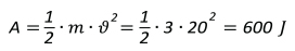
The additional power of the mechanism developed on impact will be:
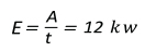
Thus, the obtained power value is sufficient for cutting branches of 0.06 meters in diameter and allows the reduction of the total power of the harvester head consumed during branch pruning. Cutting off the branches of a large diameter is carried out at the expense of several blows accompanying the cutting process.
The speed and mass of the piston can be adjusted, selecting a rational design of the device. Any efficiency of the harvester head achieved in its design can always be increased by increasing the mass of the piston, or by optimizing the gear ratio between the rollers and the pusher, without changing the mass of the piston.
CONSLUSION
Thus, as a result of the suggested construction the force of the beater impact of the delimbing knife is increased. Using this method, the branches are removed not only due to the force generated when the knives come in contact with branches pushed by the feed rolls moving the trunk, but also due to extra beater stress affecting the delimbing knife.
The use of the aforesaid method and the construction of the mechanism allows to reduce energy consumption necessary for the delimbing process. To ensure the reliability of the presented developments and field tests, further theoretical and practical research is needed.
Acknowledgment
The research was conducted with financial support by the ООО Martreyd, (a limited liability company under the laws of the Russian Federation) in the frame of the scientific and research project № 06.522/18.
REFERENCES
- POHARNIKOV FV, YUDINA NY, BULANOV AS, LADENTSOV PG 2012 Analysis of the state of the technical equipment of the forest process industry (in Russian with English summary). Lesotechnic journal 2:100-105
- №1401258 B1 EP 2007 Felling head. PITKÄNEN, HANNU ALPO ANTERO PATENT AGENCY PITKÄNEN OY - 02727625.2; appl. 30.05.2001; publ. 15.08.2007
- №3391737 A1 EP 2018 Log processing head. ALFTHAN ARTO (DE), PALMROTH LAURI (DE) – 17167284.3; appl. 20.04.2017; publ. 24.10.2018
- SYUNYOV VS, SELIVERSTOV AA 2005 Working bodies of harvesters: designing and calculation (in Russian). Petrozav. state un-t, Petrozavodsk, 204 p
- №2702865 A1 EP 2014 Harvester head and method in processing tree trunks. LASTUNEN, TURKKA (FI)– 12181988.2; appl. 28.08.2012; publ. 05.03.2014
- №9545062 B2 US 2017 Integrated hydraulic system for harvester. CALIN RASZGA, DUBUQUE, IA (US), MARK BREUTZMAN, POTOSI, WI (US) – 13/613169; appl. 13.09.2012; publ. 17.01.2017
- №3202253 A1 EP 2017 Feed means and log processing head. ALFTHAN ARTO (FI) – 17151122.3; appl. 12.01.2017; publ. 09.08.2017
- PANDUR Z, ŠUŠNJAR M, BAČIĆ M, LEPOGLAVEC K, NEVEČEREL H, ĐUKA A 2018 Fuel Consumption of Forwarders in Lowland Forests of Pedunculate Oak. South-east Eur for 9 (1): 73-80. DOI: https://doi.org/10.15177/seefor.18-07
- PONSSE 2019 Harvester heads. URL: https://www.ponsse.com/products/harvester-heads#/ (2 May 2019)
- SILVATEC 2019 Harvester heads manufacturer. URL: http://www.silvatecforest.com/home. (2 May 2019)
- JOHN DEERE 2019 Harvesting heads. URL: https://www.deere.com/en/attachments-accessories-and-implements/forestry-attachments/harvesting-heads/ (2 May 2019)
- BUDNIK PV 2012 Functional-technological analysis of harvester head (in Russian). Science and Business: Ways of Development 9 (15): 036-038
- DEMCHUK AV 2012, Modernization of the technological equipment of harvester for improving the efficiency of delivery of logs. Engineering Bulletin of Don. Volume: 20. № 2: 542-546
- №9232701 B1 US 2016 Four roller tree harvester head. ROBIN A. PETERSON, PORT ORANGE, FL (US)– 13/952164; appl. 26.07.2013; publ. 12.01.2016
- № 2513415 С2 RU 2014 Feller device for felling and limbing on tree trunks and blade for limbing. KESKINEN JUKHO (FI), KINNUNEN KARI (FI), KHANNE KARI (FI) – 2011134264; appl. 15.01.2010; publ. 20.04.2014; Bul. of invent – No. 11
- RUKOMOJNIKOV KP, VEDERNIKOV SV, GABDRAHMANOV MG 2018 A method for delimbing tree-trunks and a device for applying the method. Journal of Applied Engineering Science 16 (2): 263-266. DOI: https://doi.org/5937/jaes16-16442
- № 2676139 RU 2018 Method of developing barked assortments and working body for implementation thereof. TSAREV EM, ANISIMOV SE, RUKOMOJNIKOV KP, KONOVALOVA YA, VEDERNIKOV SV, ZABOLOTSKIJ VM, ANISIMOV NS, ANISIMOV IS – RU 2017145977; appl. 26.12.2017; publ. 26.12.2018; Bul.of invent. – No. 36
- №9999180 B2 US 2018 Timber - working head and method of operation. BRETT JAMES KAYE, TAURANGA (NZ) – 14/194314; appl. 28.02.2014; publ. 19.01.2018
- № 6318425 B1 US 2001 Delimbing device and a method in a delimbing device. PETRI NIEMI, TAMPERE – FI 09/786838; appl. 10.09.1999; publ. 20.11.2001
- №9591810 B2 US 2017 Harvester head assembly. CHAD BISBALLE, LAKE CITY, MI (US)– 14/141689; appl. 27.12.2013; publ. 14.03.2017
- ASTASHEV VK, KRUPENIN VL 2016 Ultrasonic cutting as a nonlinear (vibro-impact) process. Engineering for rural development. Jelgava, 25-27 May 2016. Jelgava, pp 218-223
- SINN G, ZETTL B, MAYER H, STANZL-TSCHEGG S 2005 Ultrasonic-assisted cutting of wood. J Mater Process Tech 170 (1-2): 42-49. DOI: https://doi.org/10.1016/j.jmatprotec.2005.04.076
- ADIKOV SG 2007 Study of the effect of tangential ultrasonic oscillations of the instrument on the efficiency of the process of machining wood (in Russian). PhD thesis, Nizhny Novgorod, Russian Federation, 188 p
- SABITOV AE 2016 Justification of parameters of perforator with shock system “piston-boom-bar” and dry blowdown (in Russian). PhD thesis, St. Petersburg Mining University, St. Petersburg, Russian Federation, 143 p
- №2682037 C1 RU 2019 Method of pruning tree branches and design of mechanism for its implementation. RUKOMOJNIKOV KP (RU), VEDERNIKOV SV (RU), GABDRAKHMANOV MI (RU)– 2017145836; appl. 26.12.2017; publ. 14.03.2019
- GOLYAKEVICH SA, GORONOVSKIJ AR 2015 Basics of designing forest machines and computer-aided design systems. Study Guide - Minsk: Belarusian State Technical University, Belarus, 126 p
© 2019 by the Croatian Forest Research Institute. This is an Open Access paper distributed under the terms of the Creative Commons Attribution License (http://creativecommons.org/licenses/by/4.0).